mBotを組み立てました。Part.2
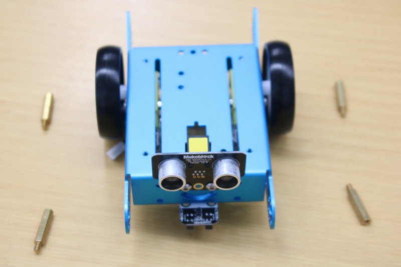
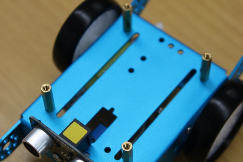
基盤を取り付ける前に土台となる柱を取り付けます。
以外と高めになるのは、このスペースに電池ケースが入る為です。
以外と高めになるのは、このスペースに電池ケースが入る為です。
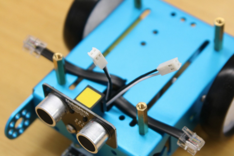
センサー類と接続するケーブルを通します。
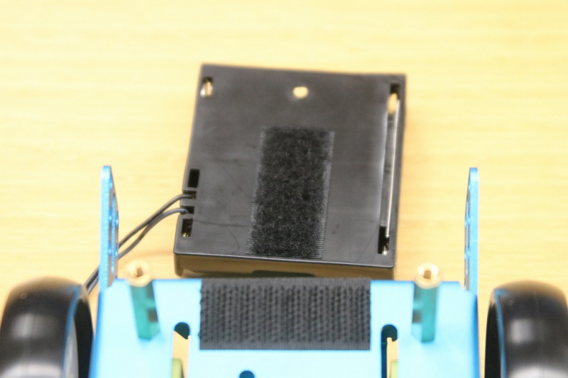
電池ケースはマジックテープで脱着できるようになっています。
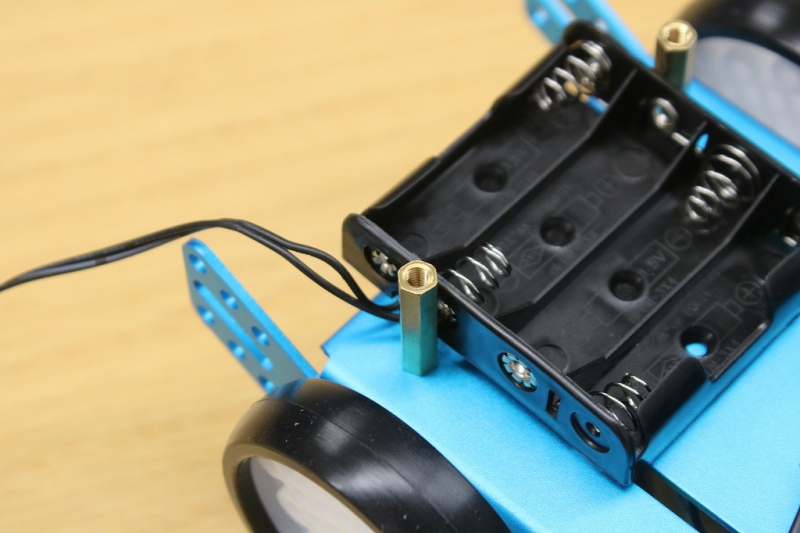
電池ケースを取り付けた所です。
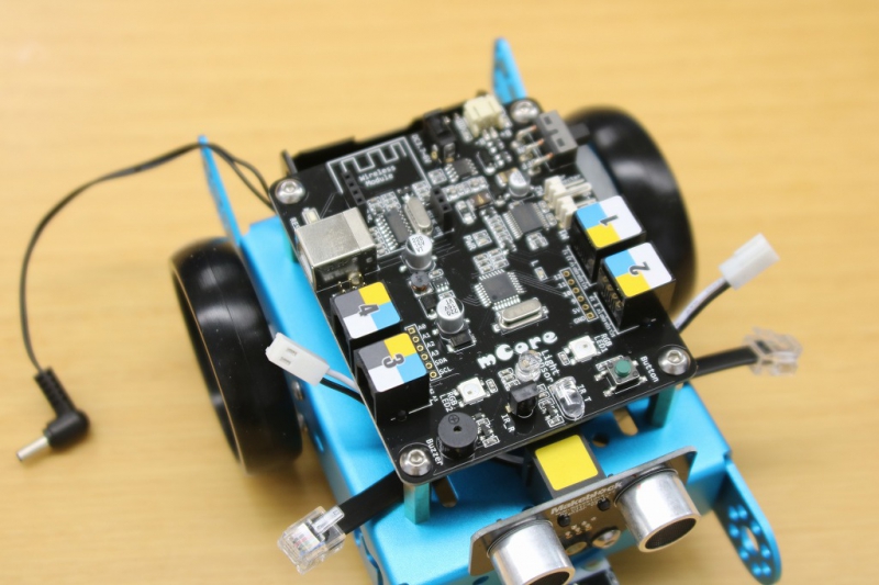
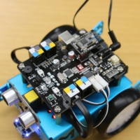
今回のメインである基盤の取付です。
今回のmBotはbluetooth版なので、bluetoothのユニットを取り付けます。
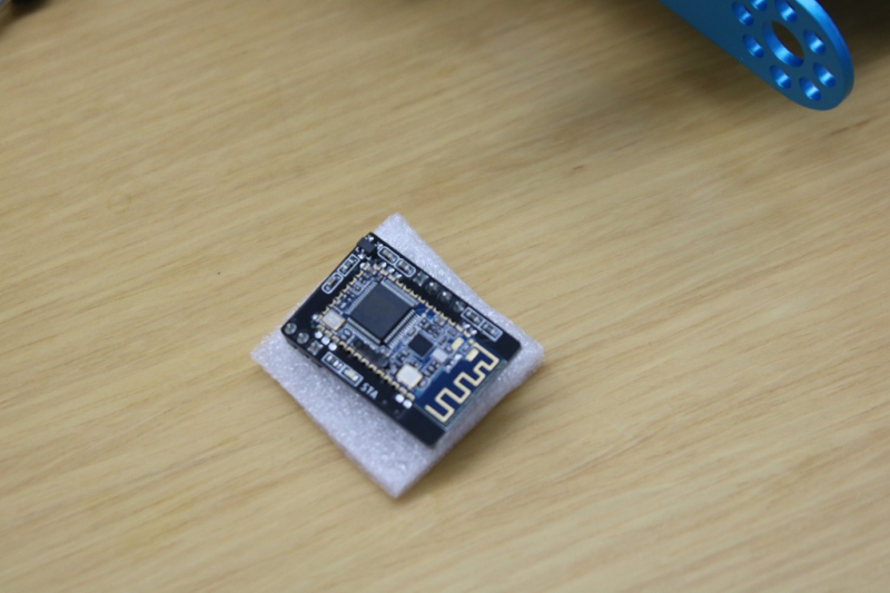
これがbluetoothのユニットです。
これがbluetoothのユニットです。
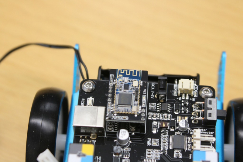
ユニットを取り付けた所
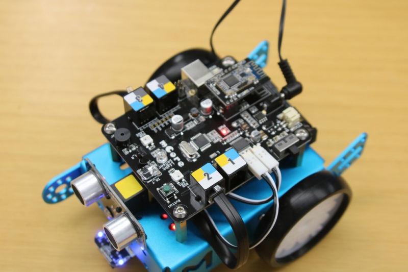
モーターの配線とセンサー類の配線を基盤に接続しました。
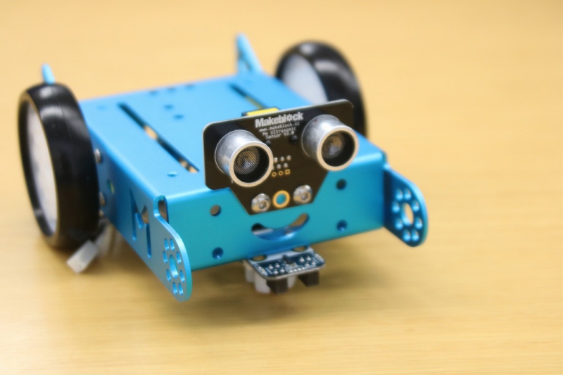
これで組み立てが完了のようです。
試しに電池を入れて、スイッチをONにしてみるとランプが点灯しビープ音(起動音?)がしました。
正常に起動したようです。
拡張パーツも多く準備されていますが、基本パーツのみだけでも様々な動きをプログラミングできるようになっています。
Labotワークショップでは「mBot」を使ったカリキュラムを用意していますので、これから紹介をしていきたいと思います。
これで組み立てが完了のようです。
試しに電池を入れて、スイッチをONにしてみるとランプが点灯しビープ音(起動音?)がしました。
正常に起動したようです。
拡張パーツも多く準備されていますが、基本パーツのみだけでも様々な動きをプログラミングできるようになっています。
Labotワークショップでは「mBot」を使ったカリキュラムを用意していますので、これから紹介をしていきたいと思います。